CrashMeTwice Disclaimer This content is NOT intended as a how-to guide but rather just a project I wanted to share on how I made it for myself. Hope it will inspire somebody.
The fabrication, modifications and designs you see on this web site are completed by myself.
If you duplicate these modifications you do so at your own risk. I do not endorse or make any claims to their safety, performance or worthiness.
Any "Product Reviews" are my sole and personal opinion. These reviews are on items purchased. If provided as a sample by a company I will clearly state this. All registered trademarks belong to their respective owners.
Simpit - Sim Rig PC
Project Initiated: 9/9/2020 - Last Updated: 10/5/2023
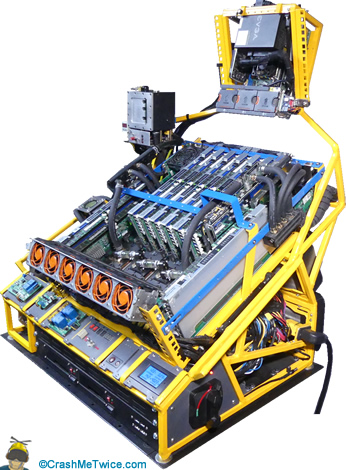
Meet theM O N S T E Rin my SimPit.
I am developing and testing software for other platforms and usually run multiple virtual machines, most are off-loaded to older machines which isn't ideal.
For my Photography hobby, post processing photos has been a drag.
New tasks have surfaced as well such as my new YouTube channel created in Dec. 2021 and with that, video editing has arrived in my office, and media editing software eats cores for breakfast, slowing the old PC to a crawl.
Simming is a great passion of mine and DCS was playable by lowering some settings, but still nothing to write home about. To sum it up, my old PC struggled under any heavier workload.
I frankly needed a new machine!
Project Goal
Building a new PC!
To create a powerful sim rig I had to think outside the box! One thing is for sure, without a great PC there is no great simming!
What I also wanted is:
>
Handle video and photo processing software with ease
>
Run multiple VRM's (Virtual Machines) in the background each using dedicated CPU's and Memory
>
Integrate a Mini-ITX system serving as a backup PC for browsing, email, and light tasks when the main system is down for maintenance or other reasons.
>
I am tinkerer therefore it has to look cool to me, build with easy access to components, and upgradeability in mind.
Or simply said, a powerful true custom build of one of a kind.
System
After month of research, browsing the web, reading and posting in forums I was truly overwhelmed.
There where so many options but none did fit all of my requests. It's was either a full out gaming PC with some capabilities for my work loads or a heavy duty workstation with some capabilities for gaming and simming.
I have lived and worked in the server world and I always have been told that servers are for work not play!
However, this is not entirely true, it's all in the configuration.
Once I started looking there I found one system which immediately stood out to me, the Supermicro SuperServer 8048B-TRFT with the X10QBI motherboard. To my knowledge it was released in April 2018 available as a complete system only.
The only problem was that I couldn't afford to buy it from Supermicro through their system integrator!
So I went to the only place most of us visit for a discount, ebay!
To my surprise, there was an abundance of parts available for this model. The first step was to figure out what was needed to build this system up and configure it for my needs. Studying the manuals, visiting server sites, and with some of my own experience I came up with this list:
To get the basic system to work all of the following was needed:
>
Motherboard: Supermicro X10QBI
>
Supermicro AOM-X10QBi-A/L module. This contains VGA, IPMI, and 10Gbe network. The motherboard will not work/boot without this module/card.
>
Four Intel Xeon E7-8891 v3, Socket LGA2011 (less cores but faster). These CPU's use a narrow ILM socket and will work only with Narrow ILM heatsinks. I make it work with the waterblocks I already have and make my own mounting brackets for them
>
Supermicro Memory Boards X10QBI-MEM1 Rev 1.01 (needed to add memory to the board. You can use 4 cards (called half load) or 8 boards (called full load). I got it to boot with one card and one CPU, two cards and two CPU's, but NOT with 3 CPU's and three cards for testing ..but what's the point?
>
Memory modules: Samsung [M393B1K70DH0-CK0] PC3-12800R ECC Reg. Server RAM seem to be the most compatible modules. I also tried Hynix 16 GB sticks and they work pretty good too. I wanted to populate all four channels for each CPU and I went with the 8GB modules. To take advantage of 2:1 Intel lockstep mode (doubles memory speed), all 8 cards need to be populated in all blue slots. That means I need 32 sticks of 8GB memory modules.
>
PSU: EVGA SuperNOVA 1600 P2 80+ PLATINUM, 1600W Fully Modular Power Supply (220-P2-1600-X1) The Supermicro X10QBI motherboard uses standard ATX type connectors. Although no one in their right mind besides me would consider a non-server power supply, I will get this going with EVGA 1600W PSU. This PSU should have enough power and connectors to make it possible.
Some more considerations:
For a motherboard like the Supermicro X10QBI I would need a boat load of fans running on high to cool. I will implement water cooling for everything what needs cooling except for the VRM's which do not have heatsinks and for now because the space within the VRM region is very small I don't think I can squeeze waterblocks into it.
After I received all parts ordered before I could begin testing I needed to convert the GPU power connectors from the EVGA PSU to be used as CPU power Connectors. I decided to use the white connectors I already had so I didn't have to order any.
What I am using here are white 8-PIN Male 5557 (4.2mm pitch) ATX CPU Power Connectors.
The modular cables on my EVGA PSU are all black. To identify the 12V carrying cables I remove them one by one with the Mini-Fit JR extraction tool and mark the 12V cables using a small piece of yellow shrink tubing.
I then stick two of the 12V pins in the CPU connector at PIN 7 and PIN 8. I am splicing the remaining third GPU 12V wire into two, crimp Mini-Fit JR pins onto it, and insert them into CPU Connector PIN7 and PIN8. I measure every cable twice with my multimeter to make sure I did not make any mistakes.
I purchased four Supermicro SNK-P0047PS 1U Passive Heatsink for CPU Socket LGA2011 Narrow ILM of ebay. These were the cheapest LGA 2011 Narrow ILM heatsinks I could find. I paid for the entire lot 30 bucks. I installed them onto the CPU's and attached with double sided 3M Acrylic tape a mix of fans onto them.
This will work fine for testing and I don't intend to put any load on the system just a basic function test.
I connect the fans to the headers and proceed plugging in the other two CPU connectors and the motherboard power connector to the motherboard.
The Supermicro X10QBI has on the AOM-X10QBi-A/L module an VGA port and that's were I plugged an old Dell monitor in for testing. I made myself familiar with the User Manual and checked that all motherboard jumpers are correctly seated on the headers and at their factory default location.
I replace the BIOS battery with a new Panasonic CR2032. I don't use the cheapos anymore as they deplete much quicker, it's just not worth it.
I am installing the memory modules onto the memory boards filling up all blue slots. I then install all memory boards into their slots.
I connect a power switch, reset switch, power LED, and a HDD LED to the motherboard's front panel header. Pretty much all Supermicro motherboards have the same header and pin-out for this header. This pre-made ATX switches come in handy for any test-setup and makes bench-testing a breeze.
I also connect a Western Digital Blue SSD to it to install Windows Server 2019 onto. I want to have an OS for testing as I will be using Supermicro's system utilities such as SuperDoctor 5 which are really nice and easy to use. It shows me all system temperatures, Fan speeds, and more. I prepared a USB key for the OS install and connected it to the USB 2.0 header on the motherboard.
I connect the EVGA power supply to the wall outlet and fire the system up. It's always a very satisfying moment when everything comes to life without error beeps or a error code on the display.
This system took almost 8 minutes! to initialize. It went to a bunch of resets. Although I knew this would happen as I read on a forum about it, it still was somewhat nerve racking.
While I was waiting, I printed the entire AMI BIOS manual out om my old PC and had it ready when the system was.
After I set everything up in the BIOS which is brutally comprehensive (not a bad thing) and two more reset's the Windows install started.
After a full test and letting it run for 24 hours I was satisfied that everything worked and shut the system down.
It was time to install all the other components including the EVGA GTX1080Ti graphics card from the old system. However, this went as smooth as butter, everything shows up and works like a charm. I am pleased but somewhat sad that I have to wait until I have made a permanent case for this awesome system.
I removed all add-on components and stuck them back into the old system for now. Bummer!
Note: I purchased my EVGA RTX3090 FTW3 and waterblocks for it while I was creating the case
Project Overview
Building the case and making it a PC:
: I make a quick hand drawing on how I want this to look. It was clear for me from the beginning that I needed this to be build from steel tubing and that this means a lot of chopping and welding.
B) Building a side structure to the right of my chair.
>
Cut wood studs and build the base structure.
>
Mount a 4080 T-Slot aluminum profiles to the structure
>
Install a20A wall receptacle and hook it up to the basement breaker panel
Note: I will update/add this part with images and video to the Walk Through (Simpit)
C) Building a side structure to the right of my chair.
Please watch the videos I have made for this project.
You can watch the videos I have made for this project on the CrashMeTwice YouTube Channel and it is also a part of a playlist named The SimPit.
Part 1 (Top Left) / Part 2 (Top Right)
Video Part 1 shows the complete build and function of my custom modded watercooled extreme PC that I use for flying my Mi-24 flight sim model in DCS World. I also use it for photo and video editing and many other tasks..
Video Part 2 shows my card I received on Patty Day. Just a few seconds of footage :)
Part 3 (Bottom Left)
Made an adjustable horizontal GPU mounting bracket to support my new RTX 4090 addition to the SimRig PC.
Video Part 4 (Bottom Right) is coming soon....
If you enjoy this project and you feel that I have earned a like from you, then you know on what to do... Thanks!
Please, leave a comment and include any suggestions or ideas you would like to share with me.
This helps quite a bit on deciding what projects are of interested to you and this allows me to share more of those in the future with you.
I really enjoy building out my simpit and adding new stuff to it.
Thanks so much of being a friend of the channel and this website.
I started out by welding up the frame and cut a plate for the giant motherboard to become a functional motherboard tray. The motherboard measures 19" x 17" (48.26cm x 43.18cm), and I wanted to have an extra half inch of room on all sides.
Afterwards I was drilling and tapping all required holes for the motherboard to be able to mount it securely onto the tray.
I then went onto the mill and cut the slots for the PCI brackets such as for the Supermicro AOM-X10QBI-A AOM card and any additional add-on cards out.
This is not an ATX, E-ATX, EEB or any other type of standardized board, it is a totally proprietary layout. I transferred every measurement from the chassis to the tray with a caliper and a machinist ruler. However, I got it right and everything fits.
Here is the motherboard mounted to the tray. I am using standard brass standoffs. I left the CPU's installed to prevent any damage to the socket pins.
I made a metal cross bar on the top for the PCI cards to be attached to. I have already drilled and tapped it but not cut to exact length. I use clamps to hold it in place before I weld on the left and right side of the tray a post on which I will be mounting the PCI crossbar.
I made the posts and clamped them left and right to the tray. I then removed the motherboard carefully without shifting the posts from their current position, went to the garage and welded them on.
I then positioned the crossbar, marked the ends, and cut them. I used my mill to drill the holes for the crossbar to mount onto the posts.
Testing! Here I have two of the 8 memory cards each holding 12 memory modules installed to make sure everything fits. I also measure the height of the Memory Cards as I will be building a crossbar for them as well to prevent them from leaning to the left or right and prevent them from damaging the memory card slots.
I made a cross bar for the memory cards and drilled holes into the memory crossbar at the location were the pins of the memory cards were located.
The posts for the memory cards were done the same way as the posts for the PCI cross bar. I welded the posts to the tray and mounted the memory cross bard to the tray.
I added two more posts made from rack rails which I had left over when creating my home lab rack to the end of the tray. This will give me a mounting option for fans which will point to the VRM chips next to the CPU's.
After about two weeks of welding, cutting, and painting the case was ready. I already installed my TEC (Thermal Electric Cooling) coolers. The paint was done with acrylic aerosol spray paint. The color is sunset yellow :)
I used half inch square steel tubing to build the case and here is another look from the side where the coolers are installed. More on the cooling later.
I'll give it a long thumbs up!
Well, my initial design for the ATX PSU (Power Supply) I wanted to use failed. Turns out that I actually couldn't find a PSU in a standard size which was powerful enough. When I ordered the EVGA 1600 Watt PSU I realized quickly it was a lot longer than standard. The bracket was cut out, re-done, and re-welded in place.
I also realized that a need more support for the tray and while I was at it, I decided to make the tray hinged. This will give me under tray access.
I made a water cooling reservoir for it from acetal (POM) and a 0.5" Lexan plate. I added an aluminum frame for looks only. The aluminum is not in contact with the water as this would be bad. I created a bracket to mount it to the frame.
TI had already a micro ATX test-station (same color) and decided to add it on top of the frame. This allows me to have a secondary system if needed. I am adding rack rails left and right to support fans and accessories I may want.
I made some hooks from 1/2" wide and 1/8" thick flat metal strips and welded them onto the frame. This will aid in cable management above the radiators.
I installed heavy duty gas pneumatic struts on each side to support the tray when lifted up. This way I can work beneath the tray without holding the heavy tray up. These are 140Nm each.
I made brackets for the industrial main power switch I will be using. This switch will reside on a plate which I bolt to the brackets. I will be installing two PSU's, the EVGA 1600W and a 1000W server PSU for the TEC's.
After a lot of sanding and prep work I finally was able to paint the frame. 6 weeks have now past since I started and I was every day in the garage from morning 'til late afternoon.
Securely mounted on top of my 14U 4-post rack and ready for components.
The DIY cooling reservoir is mounted and hooked up. I am running two 24V pumps and a digital pressure gauge next to it opens a valve to equalize pressure if it should get to low. Below the reservoir are three LED's connected to an electronic board I made which show the water level status of the reservoir. Red=To-Low, Orange=Fill, and Green=OK. In addition there are two switches, one for reservoir lighting, the other for manual pressure equalization.
The CPU's on this board use a Narrow ILM CPU socket and there are no plates available for my Swiftech Apogee HD water blocks. I went into the workshop and machined four plates for my waterblocks.
After a quick test fit they are all ready for paint. Talking about redundancy in the workshop. The first one was fun, the last one not so much :)
Remember the brackets I made for the power switch? Well I made a plate from 1/4" grey PVC and mounted the industrial power switch into. A red LED indicates that power is on.
I made a panel for System Power Monitoring (Watt & Voltage). On/Off buttons and LED's for Power, HDD, and Overheat. A vertical row with another 10 LED's are activity indicators for my eight SAS drives on which my VM's are stored.
I made a bracket and installed a Schluter 220V /25A shielded power inlet.
Next I made a plate for the pump control system. There are 4 switches each control one pump. I currently have two Koolance PMP-600 pumps with a 20L/min (5.3 gal/min) flow rate. Next to it is a LED display showing the voltage of the pumps. A 3 position main switch turns all pumps on (pos=right) or off( pos=center), or run on external power (pos=left) via the connector next to it. Perfect for a liquid change.
I have mounted the EVGA 1600W power supply onto the PSU bracket.
This is an Ambient Temperature Sensor which is mounted to the frame with a cable clamp. There is also an internal sensor located in-line to measure the liquid temperature. Both are monitored and controlled by an electronic device which in turn control the TEC's. If the temperature rises 5deg. above room temperature, the TEC's turn on, if the temperature is at or below room temperature they shut off.
The motherboard and CPU water blocks are installed. I also made two support bars between the posts for more support and to fasten tubing.
I installed four of the eight memory cards, the AOM-X10QBi-A/L module, made a liquid distribution block
Here you can see the horizontal liquid supply line. This is 1/2 ID straight copper tubing (not pipe),
Here is the hinge part of the liquid supply. It needed to be flexible therefore I made a distribution block with Tygon R-3603 tubing. You can also see the blue support bracket on which the block and tubing is mounted to.
It's time to get the power to the system. As I am using an ATX PSU on a server board I had to make several modifications to the cables. This board requires two 48-pin CPU connectors left and right to the 24-pin motherboard power connector. In addition four 8-pin CPU power connectors on the right side of the board. I converted GPU connectors to CPU connectors.
Here is the other end, the PSU side. All is wired up and ready to go.
A look below the tray. You see the power cables are routed in such way that the tray can be moved upwards and the cables follow.
I created a fan array from an old 1U Dell server. All essential components are installed and hooked up. The system is filled with liquid and all 8 memory cards are installed. I am ready to test firing the monster! All works and I let it run for about an hour, no problems.
I am installing a relay board for the pumps on the pump control panel.
I made a mounting plate for a mega sized step-up buck converter. I'll feed it the systems 12 Volt and the output is adjustable. The pumps take 24V but I will run them at 22V as they are much quieter (not quiet) at that voltage.
The buck controller is mounted on the side of the PSU bracket and wired up.
TI now make a relay control for the PWM sensor of the pumps. If I switch one pump off it would cause the system to think that the pump has failed and give out an alert. By creating a relay controlled device which connects to an PWM generator, the relay will bridge the connection from the PWM generator to the header and the system thinks all is OK.
Here are the two pumps and the relay control board wired up.
The assembly goes onto a 2U server pane; and is mounted in the bottom of the frame which has rack rails welded to it. The entire width of my frame contains server rails and practically makes up the bottom of the "case". The plumbing is done next and the system is ready for prime time.
Now I am tackling the Mini-ITX board. It is a Supermicro X10SDV-4C-TLN2F. It uses DDR4 and has a 4 core 8 threads Intel Xeon processor D-1521 embedded. I have installed two DDR4 ECC modules each with a 32GB capacity. A Nvidia Quadro P620 GPU (will upgrade later) feeds my monitors.
I am modding another Dell fan cage I got on ebay for cheap. It's cut and welded up for 3 fans.
I have installed the fan cage and added an EVGA SuperNOVA 550 GM SFX Form Factor PSU delivering 550W to the little system, more than enough!
I also added a 12V PWM fan controller to tame the loud server fans, just like on the main system.
Here is another look with everything hooked up.
It is a heavy piece of equipment!
My Sim Rig is complete, filled, and ready to roar. It was an tremendous amount of work and I still wonder to this day how I managed to take all the patience for it.
The pictures or the video don't do this system size justice with it's dimensions of a whopping 29" W x 24" D x 35" H (736mm W x 610mm D x 890 H) as this should qualify this system to be called humongous for sure.
In addition comes the impressive weight which is just about 125 lbs.!! Not your average PC to take to your local LAN party!
I also doubt that their power outlets could handle the 1.7 KW this system peaked @max. with everything running .
I really like the industrial flair this machine (maybe even call it a Mod) presents.
In a time in who everyone worries about how the color matching cable management looks in their case, have everything else color coordinated to the T, and worrying on how many RGB lights and fans one can fit into it before it's too much.
Although there is nothing wrong with that, I just want it to work, easy access to everything, and mustard and ketchup style cables have been with me for the last 30 years and grown on me :).
I actually love how it looks in every aspect of it. It's a bliss working with it.
Likely I am just out there along with the misfits but I'm honesty totally OK with that!
...and here are some more beauty shots of it.
Upgrades (Main System)
Date: Mar 17, 2023
Type: Video Card & Waterblock
GPU After a long wait and some serious budgeting I was able to purchase a RTX 4090 GPU replacing the EVGA RTX 3090 FTW3 with a GIGABYTE Gaming GeForce RTX 4090 OC-24GD graphics card.
The GIGABYTE GeForce RTX 4090 GAMING OC 24G Graphics Card is powered by NVIDIA's new RTX architecture and refined with WINDFORCE cooling technology. This GIGABYTE GeForce RTX 4090 GAMING OC 24G brings stunning visuals, amazingly fast frame rates, and AI acceleration to games and creative applications with its enhanced RT Cores and Tensor Cores, along with a staggering 24 GB of G6X memory which is awesome for DCS World modules.
Waterblock I have also installed a full coverage Bykski water block which cools the video cards core (GPU), graphics memory (RAM), and voltage regulator modules (VRM). By directly cooling these components you I have achieved a noticeable temperature drop and reach higher boosts and also extend the overall lifespan of my card by running at below factory temps.
The block is constructed of high-purity copper that is nickel electroplated to prevent oxidation. A high-flow design helps with my multiple block setup which are running in series.
This is how the Bykski water block was delivered. Well packed and included the Full Coverage GPU Water Block, a Backplate, two Stop Fittings, all the needed mounting hardware, and some thermal paste of unknown supplier. The 5v A-RGB (RBW) Light was already installed on the block.
I am removing all screws from the back plate and the PCI ports bracket I keep the screws in the same order as removed on my desk mat.
After the original fan cooler has been removed, I then clean using distilled alcohol the gpu core chip, the memory chips, and VRM's.
I now can apply a coat of thermal paste (TIM) onto the processor. My preferred thermal paste is ARCTIC MX-4 instead of the supplied from Bykski as I couldn't identify the manufacturer.
I then cut the thermal pads supplied from Bykski onto the areas as described in the install guide. I also place thermal pads onto the back plate using the old Gigabyte back plate as a placement guide.
The next step is bolting everything back together in reverse order..
The Bykski block is now installed, I am using a flashlight to look between the block and the card to check for any gaps. With this done, the card is ready for testing to make sure all the gpu's temperatures are good.
Now faced with the ludicrous Nvidia 12VHPWR 12+4 pin power connector on their 40 series cards I have decided to change my mounting solution for the GPU as this connector should not have a cable bending radius and distance to exceed.
Date: July 10, 2023
Type: PC Case & GPU Mounting Bracket
I didn't want to install my GPU vertically into the mother board on the SimRig and having the Nvidia 12VHPWR 12+4 pin power connector sticking out on top of my video card. I needed a different solution on installing it.
I decided to build a horizontal mounting bracket from scratch metal I had laying around in the shop
l started out with cutting multiple pieces of 3/4" flat steel to size and marking the metal for two holes and slots to be milled out.
I am at the milling machine and creating slots on one of the pieces which will carry the GPU to allow adjustment of the card in the X-axis.
l am drilling holes matching the ATX mounting pattern of my PCI bracket bar on the SimRig's motherboard base plate.
I went down into the garage and welded the GPU support bracket from the remaining cut metal strips to form a rectangular frame.
I then reclaimed from an old PC case a PCI slot bracket and cut it down to 3 slots but left some material for welding it to the support strip I have made. The welding was done next.
To give the GPU support at the rear, I cut another flat steel bar then is drilled for mounting it to the frame. The frame was drilled on either side in two location to allow adjustment in case my next GPU is shorter.
The parts for the assembly are now painted and laid out here. The bar on top is an old slotted router bar which will replace the existing bar aligning and supporting the memory cards.
You can see here the hole spacings drilled for the memory cards. I will be using server rack cage nuts (without their cage) as they happened to fit perfectly to fasten the GPU support bracket to it.
All fits just as intended and aligns very well.
Now it's time to mount the RTX 4090 to it. On the rear metal strip the GPU's backplate makes contact with I am sandwiching a piece of rubber material to prevent scratching.
The plumbing is done and the system filled. I had to cut some new tubing but otherwise the procedure was painless.
The electrical hook-up took a bit more effort. As I wanted to be able to switch to a different connector on the GPU if needed in the future, I decided to use two pairs of Deans connectors and splice the male end into the 12VHPWR 12+4 pin power connector.
The modded 1600 Watt server power supply also has Deans connectors to make servicing easy. The PSU is mounted to a 2U blank rack panel and can be removed with 4 bolts. I may write up in the future how I modded the PSU if there is any interest.
I am using a 20cm PCI-e Gen.4 cable to connect the GPU to the motherboards PCI-e X16 slot. Testing in 3dMark showed no performance loss in bandwith.
Well, everything works and the entire setup is very friendly to service. The entire project was done in two afternoons and I am absolutely in love with it!
...more upgrades coming soon
Performance (Main System)
Here is the result running 3DMARK's Fire Strike Ultra benchmark on 1440p.
My score was 19822.
Comparing it to my old RTX 3090 score of 12801 on the same system and monitor showed a whopping 7021 points improvement. The RTX 4090 also made my experience in DCS World Steam Edition flying the MI-24 Hind module much better. I now get an average of ~70-80FPS in Caucasus map low to the ground and heavy populated and all video settings are on max.
I am sure many of you have a gaming system which beats my score but considering that my SimRig is based on a server platform, I really couldn't be happier!
More benchmarks and a captured video flying in DCS is coming soon...
Please check back.
Performance (Mini-ITX System)
Coming soon...
Please check back.
Parts & Specifications (Main System)
Case: DIY frame constructed from 1/2" mild steel square tubing and 1/8 thick sheet metal.
Paint : Sunrise Yellow (Walmart) aerosol cans. Build-time approximately 12 weeks.
Material cost: Frame approximately: $50.00 / Paint: approximately: $30.00 Connections: MIG welded Sections: 4 (One for main system, one for Mini-ITX system, one for TEC cooling system, one for 19" rackmount accessories (front)
Dimensions: 29" W x 24" D x 35" H (736mm W x 610mm D x 890 H)
Motherboard: Supermicro X10QBI Quad socket R1 (LGA 2011) supports Intel® Xeon® processor E7-8800 v4/v3, E7-4800 v4/v3 family (up to 24-Core)
Intel® C602J chipset
4 PCI-E 3.0 16 (slot 2, 4, 9, 11), 7 PCI-E 3.0 8 (slot 1, 3, 5, 6, 7, 8, 10)
2 10GBase-T ports, IPMI LAN port and VGA port with AOM-X10QBi-A
2 SATA3 (6Gbps) ports 4 SATA2 (3Gbps) port / 6 USB 2.0 ports (4 rear, 2 Type A)
CPU's: 4x Intel Xeon E7-8891 v3, Socket LGA2011
Cores per CPU: 10-Cores / Total Threads 20
Max Turbo Frequency 3.50 GHz (Intel® Turbo Boost Technology 2.0)
Processor Base Frequency: 2.80 GHz
Cache: 45 MB Last Level Cache
TDP: 165 W, PCI Express Lanes: 32
Memory Types: DDR4-1333/1600/1866, DDR3-1066/1333/1600 (ECC Memory Supported)
Network: Supermicro AOM-X10QBi-A/L module ([VGA] / [Ethernet: Intel Intel X540 Dual port 10GBase-T Port] / [IPMI]), the board does not work without it as it also has the bus management on the card. Module was included with purchase.
External interface: USB3.2 Type A, Type C
Front interface: Type E, 19/20Pin
Compatibility: compatible with USB 3.2, 3.1, 3.0 , 2.0 , 1.1 Input interface: PCI-e X4 (X2) X8 X16
I have currently two of them in the system.
Main PSU:EVGA SuperNOVA 1600 P2 80+ PLATINUM, 1600W Fully Modular Power Supply (220-P2-1600-X1)
Fully Modular, ECO Mode, 140mm Double Ball Bearing Fan, 100% Japanese Capacitors
80 PLUS Platinum certified, with 92% (115VAC) / 94% (220VAC~240VAC) efficiency or better Connectors: 1x 24 Pin ATX / 2x 8pin EPS (CPU) / 9x 8pin PCI-e (GPU), 5x 6pin (Sata,/Perif)
AC Input : 115-240VAC, 17-10A, 50-60 Hz / DC output: +3.3V (24A), +5V (24A), +12V (133.3A), +5Vsb (3A), -12V (0.5A)
I have modded this server power supply to be specifically used for my GPU. It switches on or off with the main system. The internal 40mm fans have been removed as they producing a tremendous amount of noise. Instead I have made three cutouts in the top of the PSU chassis to accept 70mm PWM Delta fas to cool it. They are connected to a external PWM controller which I have mounted next to it.
Audio: Creative Sound Blaster X7 High-Resolution USB DAC 600 ohm Headphone Amplifier with Bluetooth Connectivity.
Ultra High Resolution Audio (HRA) 600 Ohm USB DAC and a powerful audio amplifier. Dolby Digital decoder, a 24-bit Sound Blaster Audio Processor, the Creative's CrystalVoice™, and Dual Headphone Outputs. It features the SB-Axx1™ multi-core Digital Signal Processor (DSP) and you can change the OP-Amps. Discontinued. (Please check out the Audio page )
Cooling:
CPU Waterblocks: 4x Swiftech Apogee XD (2x Limited Gold Plated edition, 2x Acetal Standard versions)
Low To Moderate Flow Restriction
Exclusive Triple Outlet Port Design
Socket *2011, 1155, 1156, 1366, *775, 771 (back-plate included / *optional)
Includes 1/2" fittings and clamps
Valve: Clippard EVO-3 12V Solenoid Valve
Model: Clippard EVO-3
Function 3-Way Fully-Ported / Poppet Travel 0.007"
Operating Pressure 105 psig (17 l/min@100 psig)
Port Size #10-32 Female In-Line
Response Time 5 to 10 milliseconds (nominal) @ 25 psig
Temperature Range 32 to 180°F (0 to 82°C)
Voltage: 12 VDC / Wattage 0.67 Watts
Reservoir: Self-made DIY
Material: Acetal (POM) for body, 1/4" Aluminum T6061 for Face plate, 1/2" Lexan plate for window
Build-time approx. 2 days
G 1/4 BSPP Ports: 5 (Fill Port, Line Out, Line In, LED Lighting, Side Port)
Capacity: 195.228ml / Chamber Dimensions: 51mmx87mmx44mm Sealing: BUNA O-Ring (Lexan against Acetal pocket)
Fans:
6x Noctua NF-A14 iPPC-3000 PWM, Heavy Duty Cooling Fan, 4-Pin, 3000 RPM, 140mm, Black (Radiators)
Brand Noctua
Item Dimensions LxWxH 5.51 x 0.98 x 5.51 inches
Power Connector Type 4-Pin
Wattage 6.6 watts
Noise Level 41.3 dB
Maximum Rotational Speed 3000 RPM
2x Scythe Kaze Flex 120mm Slim Fan, PWM 300-1800RPM Fans (Cooling Memory Cards)
Brand: SCYTHE
Power Connector Type: 4-Pin PWM
Noise Level 2.7 - 30dBA
Fan Speed: 300±200 - 1800 rpm±10%.
Air Flow: 8.28 - 50.79 CFM
Static Pressure : 0.23 - 1.35 mm H 2 O.
Voltage: 12V Dimension: 120x120x15mm (17mm with Anti-Vibration Rubber)
Delta AFB0612VHC 6cm 60mm PWM Fan 6015 12V 0.36A Ball Bearing 4pin
Power Connector Type 4-Pin PWM
Voltage:12 Volts / 1 Watt
Noise Level 38 dB
Maximum Rotational Speed 3500 RPM
1x Dell PowerEdge R720 Fan Tray Assembly with six 60mm Fans - PN3W9 - 3WNX5-A00 (VRM Cooling) Compatible with Dell PowerEdge R720 and RTX 3090
Fan Tray Assembly with 6 x system fans installed
Tray Part Number: PN3W9 / Fan Part Number: Any of 3RKJC NCJH0 WCRWR WG2CK
Tubing: Tygon Norprene A-60-G Industrial Grade Tubing 3/8" ID x 5/8" OD x 1/8" Wall (main tubing used throughout)
Copper Tubing 1/2" ID (horizontal in front of motherboard and under tray from radiators to TEC's)
Tygon Tubing R3603 (3/8 ID x 5/8" OD) (used on smaller sections and connection between CPU blocks)
Coolant: Swiftech HydrX Coolant
HydrX is a concentrated corrosion and algea inhibitor. It's formulation derives from marine engine racing applications where anti-freeze characteristics are not required, but optimum heat transfer and anti-corrosion are primordial.
Usage: For long term protection (3 years), mix (1) bottle to 0.5l (16 oz) of distilled water. / For short term protection (1 year), mix (1) bottle to 1l (32 oz) of distilled water.
Relays: Relay Module, 30A YYG-3 DC 12V Two Way Bidirectional Optocoupler Isolation
Brand Name Hilitand
This relay module uses high-quality miniature optocoupler with strong anti-interference ability and stable performance.
The optocoupler isolation relay has two modes: high/low level trigger.
Coil Voltage 12 volts
Current max.: 30 amps
Temperature Control: 5-24V 2-CH Digital LED Display Intelligent Temperature Controller with 2 probes
Channel number: 2 channel / Display mode: LED 0.36 inch, 4 bit
Sensor: Digital waterproof type DS18B20 probe(1m)
Temperature measurement accuracy: 0.1 deg. C / Resolution: 0.1 deg. C / Control return difference: 0.1 deg. C / Control range: -45C~125C
Supply voltage: 5-24V DC 0.1A / Output drive capability: 10A, 250V
12V DC Digital -50-110 °c Temperature Controller 10A Relay Module
Temperature control range: -50 ~ 110 ° C
Resolution: -9.9 to 99.9 is 0.1° C , 1 ° C temperature ranges other / Measurement Accuracy: 0.1 ° C / Control accuracy: 0.1 ° C / Hysteresis accuracy: 0.1 ° C / Refresh rate: 0.5 S / Environmental requirements: -10 ~ 60 degree Humidity 20% -85%
Input Power: DC12V
Measuring inputs: NTC (10K 0.5%) Waterproof sensor 0.5M
Output: 1 Channel relay output, capacity = 10A
Size: 48 (L) * 40 (W) * 14 (D) mm
Fan Control: TachScan-9 Fan Speed Alarm P/N 030M920-F
Supply Voltage Range: 6 to 60 VDC
Maximum Input Current: 8.0 Amps / Maximum Output Current to Any Fan: 4.0 Amps
Fan Type: DC
ACEIRMC DC12V 4-Wire PWM Fan Speed Controller Module
CPU High-Temperature Alarm with Buzzer with NTC 3950 Thermistor
Operating voltage: DC12V
Board size: 2.0 x 1.7 x 0.5inch/50mm x 43mm x 13mm
Circuit load capacity: maximum current per output 5A, the bus currents up 9A
Temperature probe parameters: 50K B = 3950
Power Control: Power Step Up Converter, DC-to-DC 4.5V-28V to 5V-35V Boost Module Regulator (used for Proteus Flow Switch)
Input Voltage: 4.5V-32V
Output Voltage: 5V-35V (adjustable) / Output Current: 4A
Efficiency: <92% / Output Ripple: <30mV / Switch Frequency: 400kHz
Operating Temperature: -40C~+85C
Size: 66*36*14mm/2.59*1.41*0.55"
DC-DC Converter Module Boost DC Step Up Voltage Regulator Module 10-60V to 12-97V 1500W 30A (used for Pumps)
Name: DC-DC 1500W Boost Converter
Input: 10-30V, 35-40A & 31-60V, 30-35A
Output: 12-97V (cannot be used to step down voltage), up to22A(please enhance heat dissipation when current is over 15A)
Quiescent Current: 15mA(when convert 12V to 20V, higher output voltage will increase quiescent current)
rating Temperature: -40 to 85C (if temperature is too high, please enhance heat dissipation)
Frequency: 150KHz Conversion Efficiency: 92% to 97%
Operating System:
Windows 10 Pro for Workstations Support for up to four CPU's and 6TB of memory
A server motherboard with 4 physical CPU sockets and 40 physical cores can't run of a standard version of Windows 10 which is limited to 2 CPU's. The only options are Windows 10 Pro for Workstations or Windows Server editions which licensing fees are not feasible for an individual and are a bit complicated as you need to install multiple licenses depending on the amount of cores per CPU.
Parts & Specifications (Mini-ITX System)
Motherboard: X10SDV-4C-TLN2F Intel® Xeon® processor D-1521, Single socket FCBGA 1667; 4-Core, 8 Threads, 45W (System on Chip)
Up to 128GB ECC RDIMM DDR4 2133MHz or 64GB ECC/non-ECC UDIMM in 4 sockets
1 PCI-E 3.0 x16, M.2 PCI-E 3.0 x4 (SATA support), M Key 2242/2280
2 10GbE LAN ports
6 SATA3 (6Gbps) ports via SoC / 2 USB 3.0 ports (rear) 4 USB 2.0 ports (via headers)
1 SuperDOM, 1 COM, TPM header, GPIO and SMbus headers / 12V DC Input and ATX Power Source
CPU: EmbeddedIntel® Xeon® processor D-1521, Single socket FCBGA 1667; 4-Core, 8 Threads, 45W (System on Chip)
Total Cores 4 / Total Threads 8
Max Turbo Frequency 2.70 GHz / Intel® Turbo Boost Technology 2.0 Frequency‡ 2.70 GHz
Processor Base Frequency 2.40 GHz / Cache 6 MB / TDP 45 W
Max Memory Size (dependent on memory type) 128 GB / Types DDR4, DDR3 / Max. Memory Speed 2133 MHz / Channels 2
Network: (Integrated) IPMI Support for IPM Interface v.2.0 with virtual media over LAN and KVM-over-LAN support
Network Controllers: Dual LAN with 10Gbase-T, Dual LAN with SoC
Single LAN with Supports 10Base-T, 100BASE-TX, and 1000BASE-T, RJ45 output,
Single LAN with 1 Realtek RTL8211E PHY (dedicated IPMI)
PSU:EVGA SuperNOVA 550 GM (123-GM-0550-Y1) Power Supply, 80 Plus Gold 550W, Fully Modular, ECO Mode
Output Wattage 550 Watts / 80 PLUS Gold certified, with 90% (115VAC) / 92% (220VAC~240VAC) efficiency or higher under typical loads / Fan Size/ Bearing: 92mm double Ball Bearing
Form Factor SFX
Item Dimensions LxWxH 10.55 x 3.82 x 7.68 inches
Audio: Creative Sound Blaster X7 High-Resolution USB DAC 600 ohm Headphone Amplifier with Bluetooth Connectivity.
Ultra High Resolution Audio (HRA) 600 Ohm USB DAC and a powerful audio amplifier. Dolby Digital decoder, a 24-bit Sound Blaster Audio Processor, the Creative's CrystalVoice™, and Dual Headphone Outputs. It features the SB-Axx1™ multi-core Digital Signal Processor (DSP) and you can change the OP-Amps. Discontinued. (Please check out the Audio page ) Switched over KVM to Mini-ITX system.
Cooling:
Fans: Delta AFB0612VHC 6cm 60mm PWM Fan 6015 12V 0.36A Ball Bearing 4-pin (Cooling CPU)
Power Connector Type 4-Pin PWM
Voltage:12 Volts / 1 Watt
Noise Level 38 dB
Maximum Rotational Speed 3500 RPM
1x Dell PowerEdge R720 Fan Tray Assembly with six 60mm Fans - PN3W9 - 3WNX5-A00 (System Cooling))
Compatible with Dell PowerEdge R720 and R720xd
Tray Part Number: PN3W9 / Fan Part Number: Any of 3RKJC NCJH0 WCRWR WG2CK
Fan Tray Assembly with 6 x system fans installed. I have removed 3 Fans and modded the cage.
Electronics:
Fan Control: ACEIRMC DC12V 4-Wire PWM Fan Speed Controller Module
CPU High-Temperature Alarm with Buzzer with NTC 3950 Thermistor
Operating voltage: DC12V
Board size: 2.0 x 1.7 x 0.5inch/50mm x 43mm x 13mm
Circuit load capacity: maximum current per output 5A, the bus currents up 9A
Temperature probe parameters: 50K B = 3950
Operating System:
Ubuntu 22.10 The latest version of the Ubuntu operating system for desktop PC's and Laptop's, Ubuntu 22.10 comes with nine months of security and maintenance updates, until July 2023.
This system is just for browsing, light tasks, or when my main system is down for a water change or maintenance I obviously won't be able to get editing software or DCS going on an Intel® Xeon® processor D-1521 CPU and a NVIDIA Quadro P620 :)
Finishing up
This was my longest project to this day. I feel really good about it as it has been an awesome experience. I learned a lot about welding on thinner material, acquired new electronic tricks, and was able to refine my patience to cosmic levels :)
Everyday I look at it and wondering how one guy in his garage can build something note worthy. I am aware that some my disagree or wouldn't like a machine like this but for me it's a piece of art.
...and now while everything has been rigged and ready, it's time for a cup of coffee (don't let me run out) ;)
I hope you enjoyed following my big Sim Rig build project!